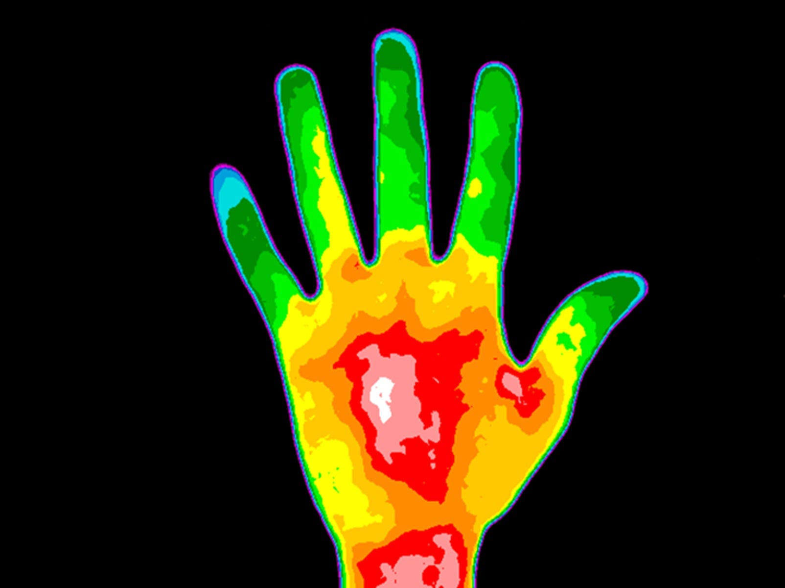
Thermography has become more affordable, easier to use and more broadly used. This means the majority of your customers have heard of it.
Applications for thermal imagers
Thermal cameras produce thermal (heat) pictures of equipment, allowing your customer’s to see the immediate benefits. In one pass through in a facility, you can usually find at least one component about to fail. This makes for a powerful demonstration and an easy business builder. Your advantage as a contractor is having broad experience with many types of equipment and failure scenarios—just like any other troubleshooting situation, the person behind the thermal camera needs to draw on experience to help analyse the readings. If this part of the panel is hot, should I investigate the connections or the load? In addition, if you’re already signed-on for regular maintenance and troubleshooting, adding thermography makes sense. You already know the facility and which units are critical to performance. You can simply add thermal inspections to your regular visits and have the tool available during troubleshooting calls. Plus, as an electrician, you’re uniquely qualified to work in live voltage situations—specialty thermographers are not and require client assistance.
Typical Applications
Electrical contractors typically use thermal imagers for predictive maintenance and troubleshooting, and sometimes during installation. For predictive maintenance, the contractor takes thermal images of key units (panels, drives, motors, etc.) at least once a year if not more often, and compares those images with each visit. Hot spots that weren’t there last time indicate problems in the making to investigate before they cause failure. Software on the thermal imager helps you align your images time after time, so that you’re making consistent comparisons.
When selling this idea to a client, here are some additional things to consider:
- - Most equipment’s failure mechanisms involve a significant rise in operating temperature long before catastrophic failure occurs.
- - Thermal images are best taken while equipment is operational. No shutdowns needed.
- - Thermal images are taken at a safe distance. Minimal safety risk (except for live voltage—that still requires full electrical safety precautions).
- - Thermal images can access components and units not otherwise measurable, such as ceiling runs.
- - Thermal measurements help detect imminent failures in nearly all types of equipment, from electrical to mechanical, process, electronic, and so on.
- - Because thermal inspections are fast, they can cover more ground and find problems in areas that would typically be ignored.
For troubleshooting, taking a thermal image of a malfunctioning unit can often identify the source of the problem—electrical hotspots can tell you which phase or connectors to check, motor hotspots can narrow it down to bearings, and so forth. Then, after repairs, follow up with another thermal image and verify that the component is no longer overheating—or that something else isn’t now overheating, instead.
Here’s a summary of principle applications.
- - Electrical power distribution systems: Three-phase systems, distribution panels, fuses, wiring and connections, substations, electrical vaults, etc.
- - Electro-mechanical equipment: Motors, pumps, fans, compressors, bearings, windings, gear boxes, and conveyors
- - Process instrumentation: Process control equipment, pipes, valves, steam traps and tanks/vessels
- - Facility maintenance: HVAC systems, buildings, roofs, insulation
How It Works:
Today’s entry-level thermal imagers are compact and easy to use with minimal training. Fluke thermal imagers include IR-Fusion®* technology that combines visual, or visible light, image with an infrared image for better identification, analysis and image management. To capture a thermal image simply squeeze the trigger. When you’re done conducting your inspection, connect the thermal imager to your computer, upload the images to the included software, analyse them more closely, and create report(s) documenting your findings. The dual images are accurately aligned which provides more details, making it much easier to spot where further investigation is needed. The next few sections in this article mention other things that need to be considered when taking a thermal images.
Emissivity
When you measure surface temperature, you’re actually reading the infrared energy emitted by that object. Emissivity tracks how thoroughly the surface emits energy. The standard emissivity of most organic materials and painted or oxidized surfaces is 0.95. However, certain materials, such as concrete and shiny metals, are poorer emitters—their emitted energy doesn’t accurately reflect their real surface temperature. To get an accurate thermal measurement of things like bus bars and any large metal electri- cal connectors, you need to adjust the emissivity value on the imager. Emissivity values for many materials are published in charts. If you can look up the emissivity value for an object, you can adjust the imager appropriately. Or, you can learn to adjust the emissivity while you’re taking the image. For example, for shiny fuse caps the emissivity might be only 0.6. If you know that, you can change the imager’s emissivity from 0.95 to 0.6 and see the real temperature.
Level and span
When the image field includes a wide range of temperatures, level and span help you focus on the most important temperatures. Most users work in automatic mode, where the thermal imager automatically assigns a temperature range based on the thermal scene it sees. If the imager senses a range from 80 degrees to 120 degrees, the camera will automatically display a temperature range between 75 degrees and 125 degrees. If, however, you look at a scene in automatic mode with something cool in the foreground and something very hot in the background, the color palette will be spread across a wide range of temperatures and the resolution will be poor. In such cases, you can manually adjust the level and span to view just the temperatures of the hot or cool object.
Pixel resolution
A high resolution screen and image looks nicer and is more impressive. However, those pixels cost money—the higher resolution your image output, the more the thermal imager is going to cost. If you’re primarily looking for hotspots in electrical and mechanical applications, chances are, you don’t really need the highest resolution available. You need enough resolution to compare one unit to another or to previous images, and that’s what the entry-level units are designed to do.
Software:
You’re going to need software with any thermal imager you buy, so here are the key points to consider. Is the software included in the price? Are future updates free of charge as well? Do you have to buy licenses for multiple team members to load it? Does it easily create good-looking reports for customers? These questions are important because good software is essential for maintaining the client relationship.
Summary:
Really, there’s nothing holding you back. Contractors can readily purchase affordable thermal imagers, quickly train on the basics, and immediately start using the tool to improve their client services. The more you use it, the more skilled you become.
*Not available on all camera models. This feature is available for all models in the included SmartView® software.
Fluke. Keeping your world up and running.®
Fluke Corporation PO Box 9090, Everett, WA 98206 U.S.A. Fluke Europe B.V. PO Box 1186, 5602 BD Eindhoven, The Netherlands For more information call: In the U.S.A. (800) 443-5853 or Fax (425) 446-5116 In Europe/M-East/Africa +31 (0) 40 2675 200 or Fax +31 (0) 40 2675 222 In Canada (800)-36-FLUKE or Fax (905) 890-6866 From other countries +1 (425) 446-5500 or Fax +1 (425) 446-5116 Web access: http://www.fluke.com
©2006-2014 Fluke Corporation. Specifications subject to change without notice. Printed in U.S.A. 10/2014 2788354c-en
Modification of this document is not permitted without written permission from Fluke Corporation


